Everything about Wedge Barriers
Top Guidelines Of Wedge Barriers
Table of ContentsWedge Barriers - An OverviewThe 25-Second Trick For Wedge Barriers

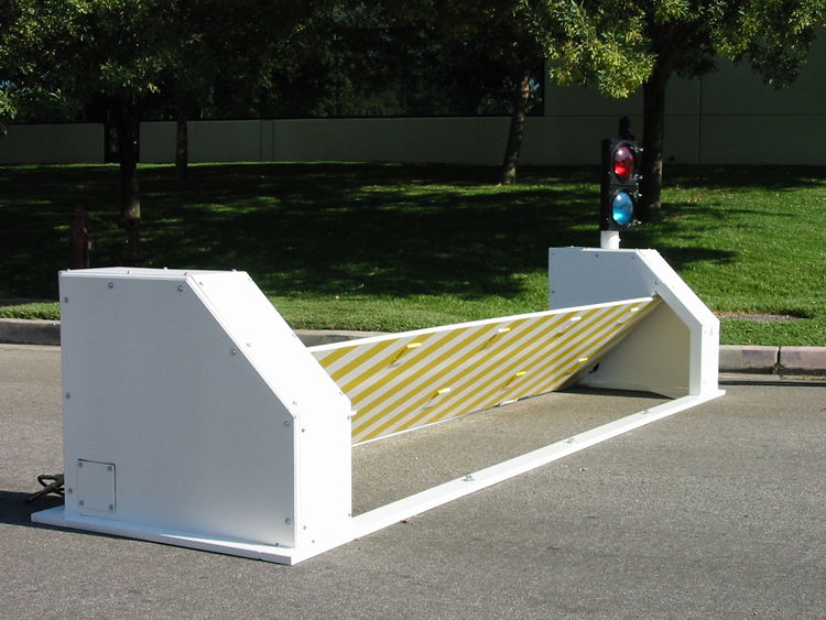
14 and the surface area 12 to which the obstacle 10 is secured may be made from concrete - Wedge Barriers. 2, the obstacle 10 is mounted to or consists of a support or subframe (e. g., support 30 received FIG. 2 )safeguarded underneath the surface area 12. The bather 10 might be bolted to the anchor or safeguarded to the anchor by other mechanical fasteners. In the illustrated embodiment, the barrier 10 consists of a wedge plate 16, that includes a portion that is substantially parallel with the surface 12 when the barrier 10 is in the pulled back position. To put it simply, lorries or people might overlook the obstacle 10 when the barrier 10 remains in the retracted setting and experience mild altitude about the surface 12 while on the barrier 10. As discussed in information listed below, when the obstacle 10 remains in the deployed placement, the wedge plate 16 is held and sustained in an elevated setting by a lifting device of the barrier 10. Additionally, the parts 18 may be bolted or otherwise mechanically coupled to one another. In this way, repair or replacement of several elements 18 may be simplified and streamlined. That is, repair work or substitute of solitary components
18 may be done quicker, quickly, and cost efficiently. FIG. In certain personifications, the support 30 might be a steel structure consisting of plates, light beams(e. g., I-beams ), and/or various other structures that are secured within the structure 14, which may be concrete. At the surface area 12, an upper side 28 of the support 30 might go to least partly subjected
, thus allowing the add-on of the barrier 10 to the support 30. g., threaded openings)in several beams or plates of the support 30 may be exposed to the surface 12. In this fashion, screws 32 or various other mechanical fasteners may be utilized to safeguard the barrier 10 to the anchor 30. As the barrier 10 is installed to the surface 12 of the foundation 14, collection of particles and various other material underneath the barrier might be decreased, and elements of the bather 10 might not be revealed to below grade environments. As indicated by reference numeral 52, the lifting mechanism 50 consists of parts got rid of below the wedge plate 16. The components 52 below the wedge plate 16 may include an electromechanical actuator, a camera, one or even more cam surfaces, and so forth. Furthermore, the lifting device 50 consists of a spring assembly 54
The spring rod 58 is combined to a camera(e. g., camera 80 displayed in FIG. 4) of the training system 50. The springs 60 disposed regarding the springtime pole 58 are held in compression by spring sustains 62, consisting of a fixed spring support 64. That is, the fixed springtime assistance 64 is taken care of loved one to the structure 14 et cetera of the bather 10.
The Greatest Guide To Wedge Barriers
The staying pressure used to
the cam web cam deploy release wedge plate 16 may might provided by an electromechanical actuator 84 or other actuator. The spring setting up 54 and the actuator 84(e. Wedge Barriers. g., electromechanical actuator)may operate together to equate the webcam and raise the wedge plate 16.
As pointed out over, the springtime setting up 54 applies a constant force on the web you could look here cam, while the electromechanical actuator may be regulated to apply a variable pressure on the web cam, consequently making it possible for the training and lowering( i. e., deploying and withdrawing )of the wedge plate 16. In particular personifications, the consistent force applied by the spring assembly 54 might be adjustable. g., electromechanical actuator) is handicapped. As will be appreciated, the spring assembly 54 may be covered and safeguarded from debris or other components by a cover plate(e. g., cover plate 68 displayed in FIG. 4) that might be considerably flush with the raised surface 38 of the structure 14. As stated over, in the deployed placement, the wedge plate 16 offers to block accessibility or traveling past the barrier 10. As an example, the barrier 10(e. g., the wedge plate 16 )might obstruct pedestrians or lorries from accessing a residential property or path. As talked about above, the obstacle 10 is attached to the anchor 30 protected within the foundation 14,
front braces 71. Because of this, the affiliation settings up Your Domain Name 72 may pivot and revolve to make it possible for the collapse and extension of the affiliation settings up 72 throughout retraction and release of the bather 10. The affiliation settings up 72 reason motion of the wedge plate 16 to be restricted. As an example, if a vehicle is taking a trip in the direction of the released wedge plate 16(e. As an example, in one scenario, the safety legs 86 may be extended throughoutmaintenance of the barrier 10. When the security legs 86 are deployed, the safety and security legs 86 sustain the weight of the wedge plate 16 against the surface area 12. As a result, the training device 50 might be shut off, serviced, eliminated, changed, and so forth. FIG. 5 is partial perspective sight of an embodiment of the surface-mounted wedge-style barrier 10, showing the web cam 80 and the webcam surface areas 82 of the lifting mechanism 50. Especially, 2 web cam surface areas 82, which are described as lower webcam surfaces 83, are positioned below the web cam 80. The lower cam surfaces 83 may be taken care of to the surface area 12 (e. For example, the reduced cam surface areas 83 and the placing plate 85 may develop a single piece that is safeguarded to the anchor 30 by screws or other mechanical bolts. Additionally, 2 web cam surface areas 82, which are referred to as top cam surfaces 87, are positioned over the cam 80 and combined to (e. In other embodiments, intervening layers or plates might be positioned between the surface 12 and the reduced webcam surfaces 83 and/or the wedge plate 16 and the top webcam surfaces 87 As stated above, the webcam
80 equates along the webcam surfaces 82 when the wedge plate 16 is lifted from the withdrawed setting to the released setting. Additionally, as stated above, the springtime setting up 54 (see FIG. 3 )may provide a force acting on the cam 80 in the direction 102 through spring rod 58, which might decrease the force the click here to read electromechanical actuator 84 is called for to put on the web cam 80 in order to activate and lift the wedge plate 16. 1 )to the deployed position(see FIG. 4). As revealed, the webcam 80 includes track wheels 104(e. g., rollers), which contact and equate along the cam surfaces 82 throughout operation.